Ardupilot CAN Bus Setup
CAN Bus Setup
This article shows how to setup CAN bus and what options users have to accomplish the setup suitable for their specific needs.
Tip
The UAVCAN setup page is here. But the parameters below must be configured correctly in order to use the UAVCAN driver.
Overview
A Controller Area Network (CAN bus) is a robust vehicle bus standard designed to allow microcontrollers and devices to communicate with each other in applications without a host computer. It is a message-based protocol, designed originally for multiplex electrical wiring within automobiles to save on copper, but is also used in many other contexts.
All nodes are connected to each other through a two wire bus. The wires are 120 Ω nominal twisted pair.
Most autopilots that run ArduPilot have either one or two CAN interfaces for connection of different devices. ArduPilot can support up to 3 CAN interfaces. The setup of the interfaces can be made in a way that will provide redundancy or maximum throughput or a mix of both. This is accomplished with a three layer approach, where apart from the physical interface there exists a driver layer that represents a specific protocol and a software layer (ArduPilot) that communicates on CAN bus through these drivers.
Each physical interface can be virtually connected to one of up to three drivers that represent the protocols to be used. For example, the most common scenario will be with all interfaces connected to a UAVCAN driver. Such setup will provide redundancy for devices with up to three CAN interfaces and full functionality for devices with one CAN interface.
Configuration settings
Enabling CAN interfaces
Each physical port can be turned off or connected to corresponding driver with parameter CAN_Px_DRIVER, where x is the number of the CAN port. The value of this parameter is the id of driver that will be associated with this port (interface).
For example, the most common setup will have one driver and all interfaces will be connected to it. The CAN_P1_DRIVER and CAN_P2_DRIVER parameters in this configuration should be set to 1 (first driver). And that driver ( CAN_D1_PROTOCOL) be set to 1 (UAVCAN).

After change of any CAN_Px_DRIVER or CAN_Dx_PROTOCOL the autopilot has to be rebooted for the changes to take place.
Configuration of CAN interfaces
After enabling the interface and reboot two more parameters can be set for each of the enabled interfaces.
These are:
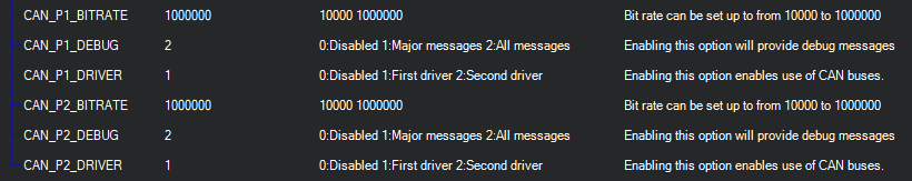
CAN_Px_BITRATE - sets the desired rate of transfer on this interface
CAN_Px_DEBUG - allows output of debug messages
Usually the bitrate used by default is 1 Mbit. Debug level can also be set on user’s preference and needs.
When any of the interfaces are associated with any driver, that driver will be loaded with specified protocol.
Configuration of CAN driver
The driver should be set to use some protocol. Currently there is support for UAVCAN devices, which is numbered 1, and numerous CAN ESCs. The parameter CAN_Px_PROTOCOL, where x is the number of driver, should be filled with the number of protocol for this driver.

After the change to protocol the autopilot has to be rebooted for the changes to take place.
CAN ESCs
Several types of CAN based ESCs are supported: UAVCAN, KDECAN, ToshibaCAN, and PiccoloCAN. For these ESCs, each type use several parameters for configuration. See the ESC’s individual description page here.